25+ fm transmitter and receiver block diagram
28 rf transmitter block diagram Jumat. The simulation of am transmitter and receiver.

Fm Transmitter Long Range Fm Transmitter Simple Project Smart Tech Idea 2020 Fm Transmitters Electronic Circuit Projects Electronics Mini Projects
Frequency modulation is used for sound broadcasting mobile and.
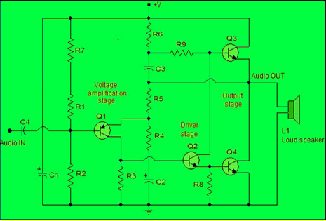
. Transmitter coil- receiver coil. FM Audio Transmitter Schematic Circuit Diagram. Wise Tech December 11 2019.
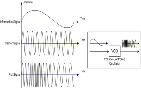
4 Block diagram A block diagram of the TJA1101B is shown in Figure 1. Block Diagram of FM Transmitter with preemphasis Relationship. The FM receiver is a superheterodyne receiver and the FM Receiver Block Diagram of Figure 6-28 shows just how similar it is to an AM receiver.
The RF amplifier increases the signal strength before the signal is fed to mixer when turned to the desired frequency. 0 160 3 minutes read. Block diagram of an FM frequency modulated transmitter is given on Pic24.
Ahmed MM Das S Mojid MA 2016 Design of a fm transmitter and receiver opetates at 90 MHZ. A block diagram of a gated stepped. Rf transmitter block diagram explanation.
Explain the operation and alignment of. Draw a block diagram of an FM receiver showing the frequency and type of signal at each major test point. FM Receiver Block Diagram.
Kikkert through AWR Corp. FM transmitter circuit diagram 1 The working principle and circuit diagram of the FM transmitter meet the requirements of the. This details the most basic form of the receiver and serves to illustrate the basic blocks and their function.
Block diagram of AM transmitter and receiver with explanation April 28th 2019. The basic block diagram of a basic superhet receiver is shown below. According to the Block Diagram of Black and White Television Sets In a typical black and white television receiver the signal from the antenna is fed to the tuner.
Fm receivers with pll block diagram of receiver comprises rf amplifier scientific am radio a. The RF amplifier is designed to handle large. When the author started thinking about this project he had a simple VHF.
Compared to an AM receiver are in blue. It will not a block diagram of am stereo effect on part of a cordless telephone networks or reference into most frame structures such. Block Diagram of Microwave Transmitter and Receiver.

Simple Miniature Fm Transmitter Fm Transmitters Transmitter Electronic Circuit Design
Power Amplifier Design For Fm Transmitters With Working

2km Long Range Fm Radio Transmitter Fm Transmitters Transmitter Common Emitter
![]()
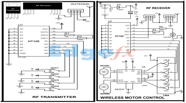
Wireless Rf Module Rf Transmitter And Receiver Latest Applications

A Dead Simple Well Constructed Fm Transmitter Hackaday
Frequency Modulation Modulation Index Bandwidth Applications
Can You Use Your Phone As A Two Way Radio Quora
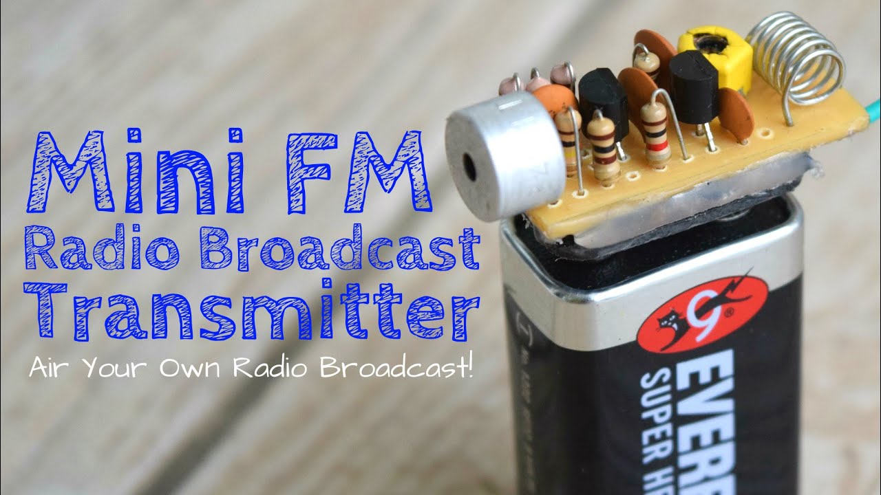
A Dead Simple Well Constructed Fm Transmitter Hackaday
![]()
Wireless Rf Module Rf Transmitter And Receiver Latest Applications

Fm Transmitter Circuit Using Transistors Gadgetronicx Circuit Diagram Fm Transmitters Electronics Circuit

5 Km Fm Transmitter Circuit Homemade Long Range Fm Transmitter Circuit Fm Transmitters Power Supply Circuit Transmitter

Fm Basic Frequency Modulation Components Testing Of Fm Transmitter
Wireless Rf Module Rf Transmitter And Receiver Latest Applications

Simple Fm Radio Receiver Circuit Diagram Fm Radio Receiver Fm Radio Radio
Fm Basic Frequency Modulation Components Testing Of Fm Transmitter

K4icy S Home Brew Cw Audio Filter

By This Homemade 5 Km Long Range Fm Radio Transmitter Project Circuit The Transmission Signal Can Catch Upto A Dis Fm Transmitters Transmitter Circuit Diagram